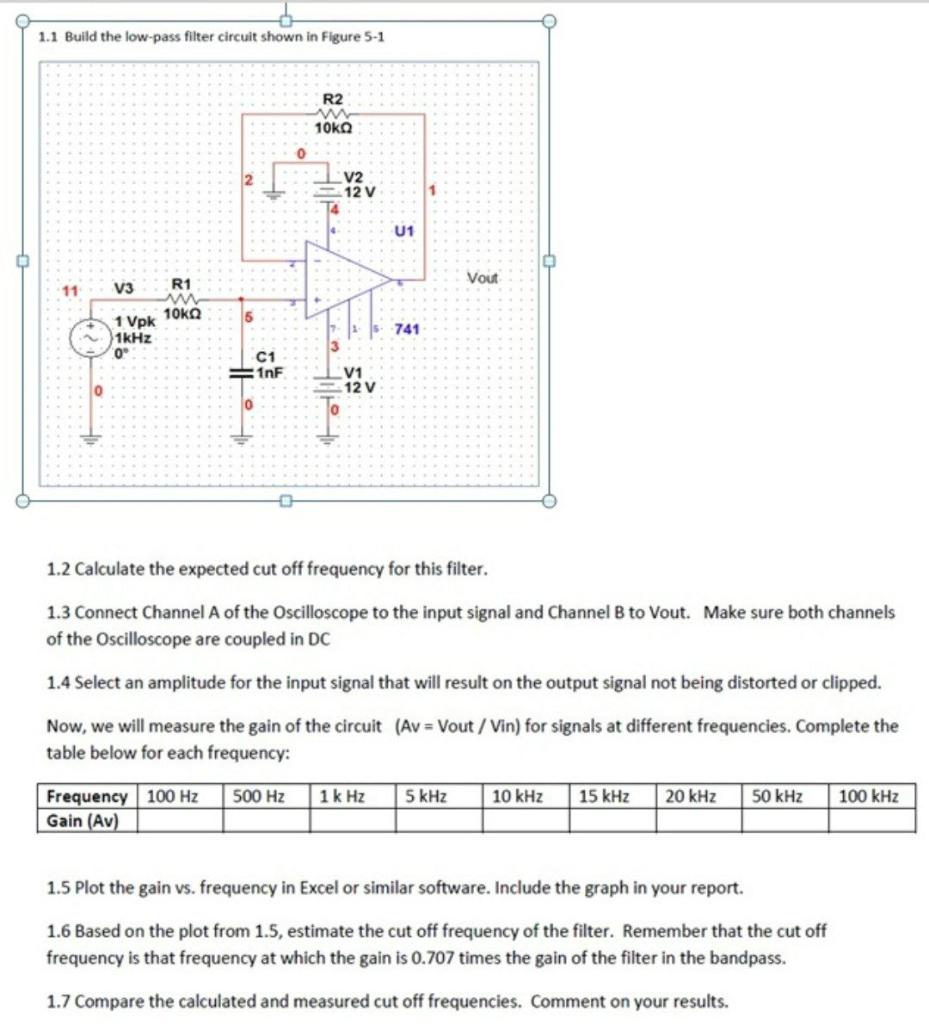
Solved 11 Build the lowpass filter circuit shown in Figure Circuit Diagram
Solved 11 Build the lowpass filter circuit shown in Figure Circuit Diagram To surmount this problem, active circuit designs were introduced. When a passive low pass filter is connected to an Op-Amp either in inverting or non-inverting condition, it gives an active low pass filter design. The connection of a simple RC circuit with a single Op-Amp is shown in the image below.. First Order Active Low Pass Filter with the frequency response The following images depict the standard opamp based low pass filter circuits. The first one needs to be powered by a dual supply, and the second one works using a single supply voltage. Designing a Customized Low Pass Filter Circuit Active Low Pass Filter Example No1. Design a non-inverting active low pass filter circuit that has a gain of ten at low frequencies, a high frequency cut-off or corner frequency of 159Hz and an input impedance of 10KΩ. The voltage gain of a non-inverting operational amplifier is given as:
Designing a low-pass filter circuit may seem straightforward on the surface, particularly when approached from an instructional perspective. However, if you're in the expert's shoes, you'll understand how rigorous the thought process is to design an effective lowpass filter circuit. Even the most experienced RF and electrical engineers

What Is a Low Pass Filter? A Tutorial on the Basics of Passive RC ... Circuit Diagram
The formula and schematic for the LC low pass filter: Let's analyze a low pass filter with a practical example : Q. Design a low pass filter having cutoff frequency 'fc' = 75MHz and Vin = 5 volts using RC filter? Solution: given -> f = 75Mhz. R = 100 Ω(assumed)——-
This article explores the analysis and design of passive low-pass filters. These circuits play an important role in a wide variety of systems and applications. The RC Low-Pass Filter We can attempt to create a second-order RC low-pass filter by designing a first-order filter according to the desired cutoff frequency and then connecting two A low-pass filter (LPF) is designed to pass all frequencies below the cut-off frequency and reject all frequencies above the cut-off frequency. It is simply an RC series circuit across the input, with the output taken across the capacitor. At the cut-off frequency, the capacitive reactance of capacitor C is equal to the resistance of resistor R, causing the output voltage to be 0.707 times the