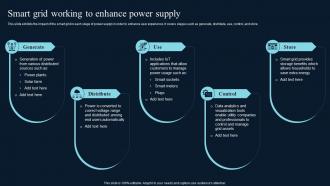
Smart Grid Working To Enhance Power Supply Comprehensive Guide On IoT Circuit Diagram
Smart Grid Working To Enhance Power Supply Comprehensive Guide On IoT Circuit Diagram Wondering if anyone could help me find the best match for my needs. I am wanting to put a power strip in a location that is a pain to get to. Since it will allow me to turn on/off other smart home devices (e.g. Hue, Bond, Harmony, etc) I would like the following in order of priority: North American plugs Individually controllable plugs
This is the complete circuit diagram for this home automation project. I have explained the circuit in the tutorial video. The circuit is very simple, I have used the GPIO pins D23, D22, D21, D19, D18, D5, D25 & D26 to control the 8 relays.. And the GPIO pins D13, D12, D14, D27, D33, D32, D15 & D4 connected with push buttons to control the 8 relays manually.
![[PDF] SMART POWER INTEGRATED CIRCUITS Circuit Diagram](https://d3i71xaburhd42.cloudfront.net/fa2a2c07f9eb894079a6634b44f3ef633412baa8/4-Figure4-1.png)
IoT Power Outlet with CircuitPython and Adafruit IO Circuit Diagram
In this tutorial, we'll be using a 5V relay to switch the current to a power outlet on and off. We'll use the Arduino and a sensor to control when the relay switches. To learn more about the 5V relay and it's different modes of operation, see our article "How to Set Up a 5V Relay on the Arduino". We could always wire the relay directly to the device we want to control, but it's
The Kicad files of the circuit can be found in the power_strip_kicad folder at. Step 4: Preparing the Power Strips. Modifying the power strips is pretty straight forward. As can be seen both the power strips have switches for each socket. The IoT power strip project also uses the same node-red and MQTT instances. Step 11: Suggestions for
Powerstrip with individual and local control via Home Assistant Circuit Diagram
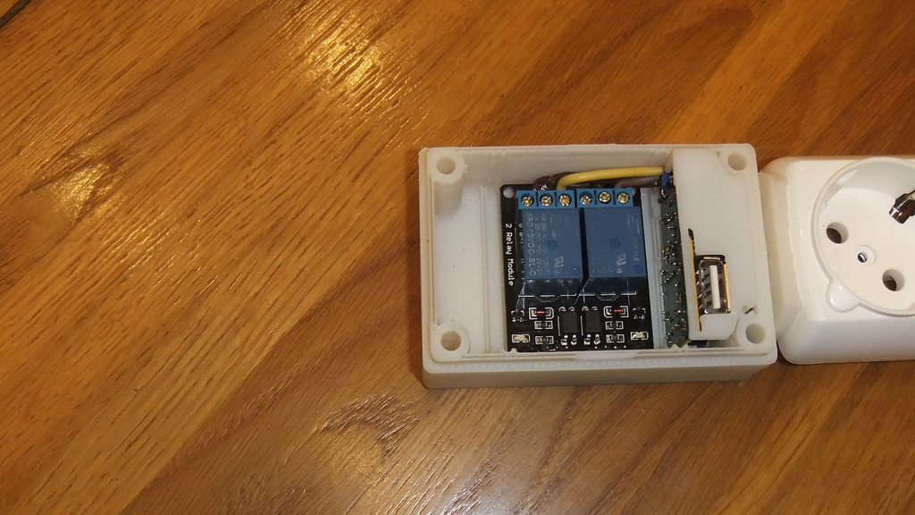
A year ago I decided to make a simple device with a web interface for reliably turning on/off a couple of mains sockets via Wi-Fi. I thought that ESP-01 (having GPIO0 and GPIO2 available), and 2-channel Relay Module would be enough for that, and with NodeMCU writing a software would be not a problem at all.. During the prototyping of the device, the set of requirements were expanded a little:

The Internet of Things (IoT) has transformed the technological landscape, enabling the creation of smart devices and interconnected systems that enhance our daily lives and industrial processes. Arduino, a versatile and open-source electronics platform, is at the forefront of this revolution, providing a robust foundation for developing a wide Figure 1 illustrates the simplified functional block diagram for the IoTtalk platform, which consists of the IoTtalk server (Figure 1 (a)), the IoT devices (Figure 1 (b) and (c)), and possibly a Build an open-source version of an internet-controlled outlet using a PyPortal and a power relay. The outlet is programmed with CircuitPython and connected to Adafruit IO so you can control it from anywhere in the world! Go further with this guide by adding a feedback indicator so you read the appliance power status.
