Op Amps Basics PHC504 Circuit Diagram
Op Amps Basics PHC504 Circuit Diagram Hi, thanks for watching our video about active filters! In this video we'll walk you through:- How to design, simulate and build active opamp filters- Using
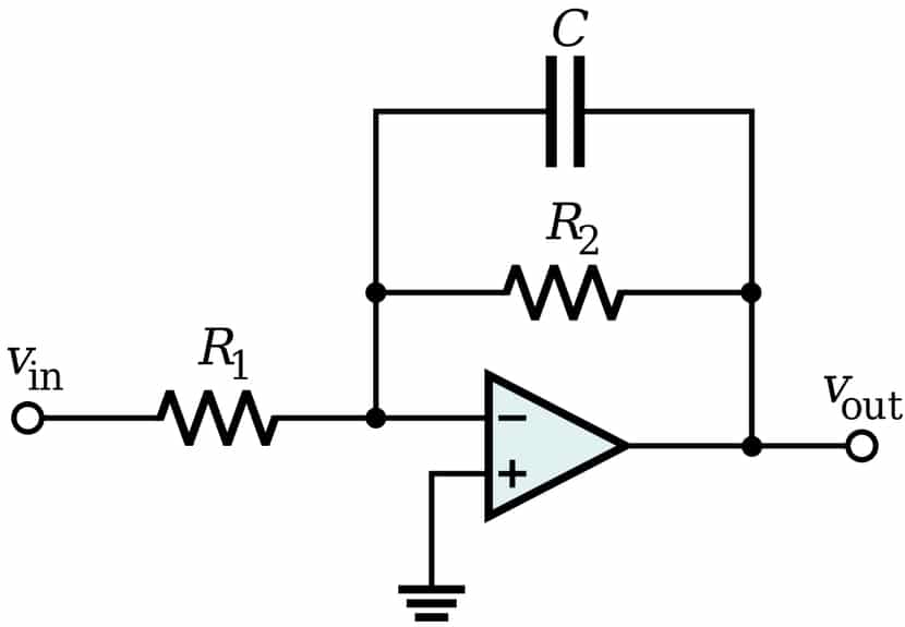
Applications of Active Low Pass Filters are in audio amplifiers, equalizers or speaker systems to direct the lower frequency bass signals to the larger bass speakers or to reduce any high frequency noise or "hiss" type distortion. When used like this in audio applications the active low pass filter is sometimes called a "Bass Boost" filter. In an active low pass filter, the peak of the passband of the filter can be much larger than the input voltage signal because there is amplification. For passive low pass filters to be built, all that is required are resistors and capacitors. Active low pass filters require either transistors or op amps to provide amplification to the circuit. As you can see, it requires only one op-amp, two resistors, and two capacitors. We call these filters "active" because they include an amplifying component. There are two feedback paths, one of which is directed toward the op-amp's non-inverting input terminal. We're accustomed to analyzing op-amp circuits that have only negative feedback.

OPAMP101 Low Pass Active Filter Circuit Diagram
Active Low-Pass Filter Design Jim Karki AAP Precision Analog ABSTRACT This report focuses on active low-pass filter design using operational amplifiers. Low-pass filters are commonly used to implement anti-aliasing filters in data acquisition systems. Design of second-order filters is the main topic of consideration. 5/4/2020 Active Low Pass Filter - Op-amp Low Pass Filter https://www.electronics-tutorials.ws/filter/filter_5.html 1/8 Home / Filters / Active Low Pass Filter
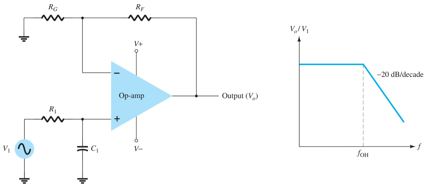
Active filters are introduced to overcome the defects of passive filters. A simple active low pass filter is formed by using an op-amp. The operational amplifier will take the high impedance signal as input and gives a low impedance signal as output. The amplifier component in this filter circuit will increase the output signal's amplitude. The basic configuration for an active low-pass filter using an operational amplifier is as follows: Place the operational amplifier (op-amp) on a breadboard. Connect a resistor (R) between the input signal source and the non-inverting input (V in) of the op-amp. Connect a capacitor (C) between the non-inverting input and ground.