Make It Smart Light Project at Lets Get Hacking a community for Circuit Diagram
Make It Smart Light Project at Lets Get Hacking a community for Circuit Diagram Here is my answer in a few word "Cayenne is an MQTT based drag and drop IoT platform to build IoT based projects.Like Blynk IoT platform" In order to use cayenne first, you need to create a Cayenne account SignUp if you already have an account then login to your account. Click 'Add New ' add new
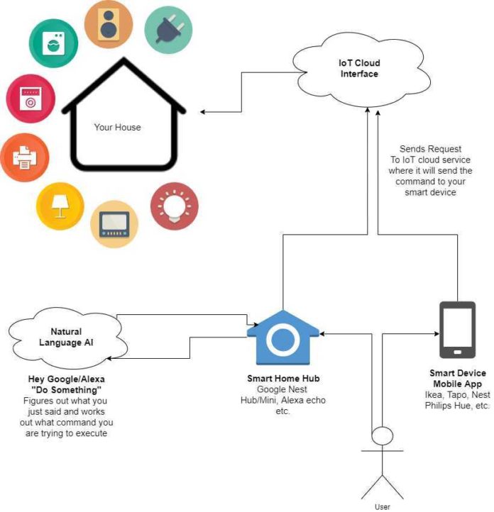
IoT project of controlling home light using WiFi Node MCU, and Relay module. In this project, we are going to build a home light controlling system using the Wi-Fi network or Internet (Mobile data). Using this project we are able to control our home light from anywhere in the world. Smart Control systems have been much necessary for better control and optimal usage of resources like electricity, water, etc. in our day-to-day life. Every system would start with the smallest automated device. A smart light System is one such part of a big #Automation system that gives an idea of how such a system works and how it is analyzed.

Based Smart Light System Circuit Diagram
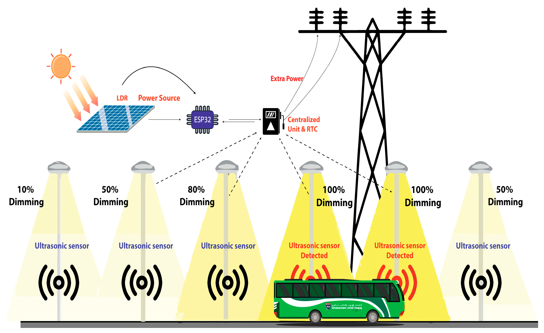
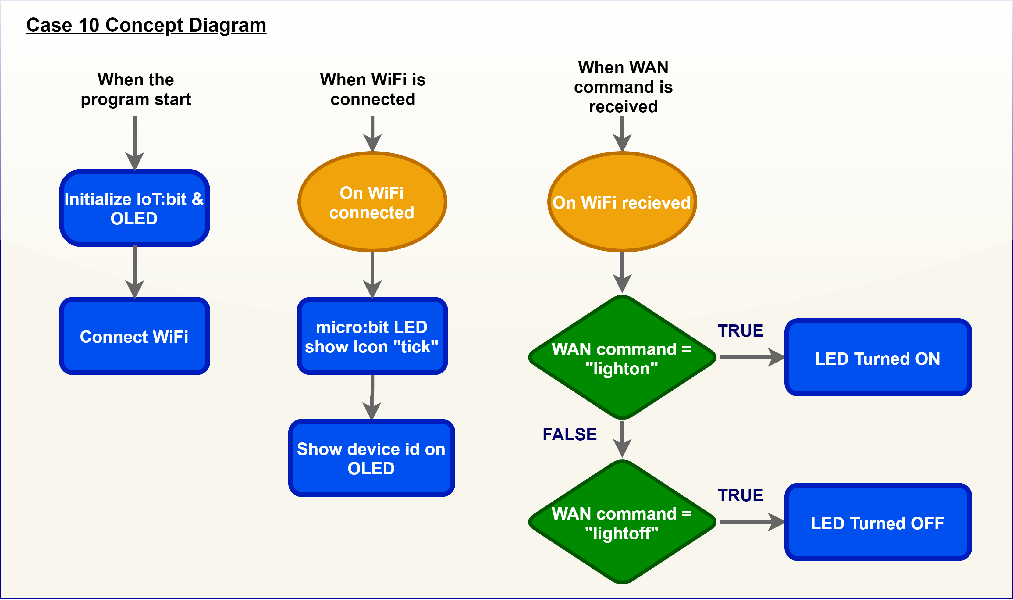
In this tutorial, we are going to make an IoT based Smart Traffic Light system. We will connect the lights by using ESP32. Let's begin! Contents: Introduction; Materials Required; The Circuit; Code and it's Explanation; The Final Run; Introduction. First of all, we will create a web server using ESP32. Smart Street Light Using NodeMCU and IOT ThingSpeak: There have been a limited number of streets in smart societies, and over the last few decades, street lamps and management regulation have been relatively simple. (A0) which is connected to point between fixed resistance and one end of the LDR sensor as shown in the circuit diagram. Since
![[PDF] Iot Based Smart Street Lights Empowered By Piezoelectric Sensors ... Circuit Diagram](https://d3i71xaburhd42.cloudfront.net/04d4a1744b678359007c75353dfdbe7907d00e2e/3-Figure6-1.png)
Use a diode bridge rectifier to convert AC voltage from the PZTs to DC. Add a capacitor to smooth the DC output if possible. Energy storage circuit: Feed the smoothed DC voltage into a rechargeable battery. Include a voltage regulator to ensure consistent output for the, Arduino Mega, ESP-01 and LED lights. IoT control circuit:
Smart Traffic Light System using NodeMCU (ESP32) Circuit Diagram
Components Required. To build the IoT-Based Smart Light System, the following components are essential: ESP32 Microcontroller: The brain of the system, used for wireless communication and control.; 1-Channel Relay Module: Acts as a switch to control the light.; Light Bulb: Represents the load in the system.; Power Supply: Supplies power to the ESP32 and relay module. Automatic Street Light Control Circuit Diagram. Iot Based Smart Lighting And With Weather Include Street Lights System. Digital Logic Circuit Question 3. Solar Powered Led Street Light With Auto Intensity Control. Smart Street Light System Using Ir Sensor And Arduino Electroduino. Automatic Street Light Circuit Diagram Using Ldr And Relay I made an app just for this project to make it as easy as possible to control the lamp to your liking. The smart lamp can really be controlled by anything capable of sending an http GET request. This means the lamp accepts commands from nearly a limitless array of devices. 3D Printing. This smart lamp deserves a cool looking case.
In this project we are demonstrating the prototype of the Smart Street Light with 3 IR sensors, 1 LDR sensor and 3 LEDs - each representing one street light. We will also update the LDR sensor data to the ThingSpeak and control the LEDs (Street lights) over the internet from anywhere in the world.