How to make Electric Bike Motor Controller using Arduino Circuit Diagram
How to make Electric Bike Motor Controller using Arduino Circuit Diagram The speed is controlled through an externally applied varying DC voltage source. The most striking feature of this circuit is its ability to provide full torque even at minimum motor speeds. Complete circuit diagram for the motor controller along with the parts list has been included here.
Electric motor speed controller. In this video we learn how to design a simple PWM speed controller for a DC motor learning how current flows in the circuit
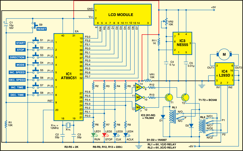
How to Build a High Torque DC Motor Speed Controller Circuit Circuit Diagram
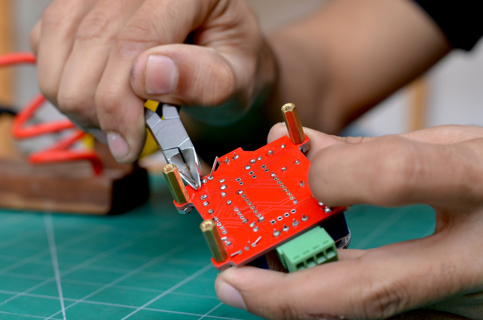
Before powering the circuit check everything for short circuits, faulty wiring and also check for correct input polarity (Vcc & ground). Then power the circuit. If THE MAGIC SMOKE hasn't appeared and the motor is spinning and everything is perfect, then turn the pot shaft to check for the change in speed as you turn it. Do not overload the circuit! How to Make a Motor Control Board | Step-by-Step GuideIn this video/article, we will learn how to make a motor control board. It covers the required componen 5 easy to build speed controller circuits for DC motors are presented here, first one using MOSFET IRF540, second one using IC 555, the third concept with IC 4093, fourth design involves the IC 741, while the fifth design utilizes IC 556, featuring torque processing Hi, so I have a question about why all DC electric motor controllers on the
Learn the basics of the electric motor speed controller. In this article we learn how to design a simple PWM speed controller for a DC motor learning how current flows in the circuit and what each component does. You can even build the circuit yourself! Scroll to the bottom to watch the YouTube tutorial.
Designing a Speed Controller for DC Motor Circuit Diagram
The Arduino can provide a maximum of 40mA at 5V from its pins. As most motors require more current, the TIP120 transistor acts as a digital switch to control the motor with higher electrical requirements. Ensure that the diode is placed in the correct orientation to prevent back-emf damaging the transistor when the motor turns off. Motor speed controller tutorial - PWM how to buildElectric motor speed controller. In this video we learn how to design a simple PWM speed controller for a D
