How To Make A Radio Frequency Jammer Circuit Diagram
How To Make A Radio Frequency Jammer Circuit Diagram 2. DESIGN: The jammer design includes a capacitor, resistor, inductor, transistor, and NE555 timer IC to block the signal and amplify the generated signal from 800 MHz to 1.4 GHz, the same as a cell phone signal [14]. Fig 1- Design of Jammer 3.SIMULATION: Porteous software was used to simulate the jammer. All the Building a mobile jammer requires a deep understanding of radio frequency (RF) engineering in Electronics. It involves complex circuit design, component selection, and testing. Essential components include oscillators, power amplifiers, antennas, and filters. Circuit design requires precise calculations. Circuit 1: Mobile Jammer Circuit using 555 The document describes how to build a simple homemade RF signal jammer circuit that can jam RF signals within a 10 meter radius. It explains the circuit diagram and components, including two transistor oscillator and amplifier stages. It provides specifications for jamming different frequencies by adjusting inductors and trimmers. The document also discusses how to optimize the circuit by

Cell Phone Signal Jammer Working . RF amplifier circuit comprises transistor Q1, capacitors C4, C5, and resistor R1. This RF circuit amplifies the signal generated by the tuned circuit. The amplified signal is given to the antenna through capacitor C6. It blocks DC and allows only the AC component of the signal to be transmitted. 4 Testing and Using the Signal Jammer. 4.1 Checking for Interference; The purpose of the circuit is to create a device that can block or disrupt the signals from cell phones, radios, and other communication devices. Here is a list of materials you will need to make a homemade signal jammer: Radio Frequency (RF)
How to Make a Signal Jammer: A Step Circuit Diagram
In this project, I'll show you how to create a powerful homemade signal jammer capable of interfering with various types of signals, including drones, Wi-Fi, and 4G networks. We'll explore the necessary components, such as high-voltage modules, circuit boards, and aluminum antennas, while covering key steps for both a basic and an advanced Source of Interference (usually built into the Tuning Circuit) RF Amplification Unit (the so-called "amplifier stage") Transmitting Antenna; The VCO is the most important part. It is like the heart of your jammer. The VCO produces an RF signal that will communicate with the device being blocked. First of all, you must select the frequencies
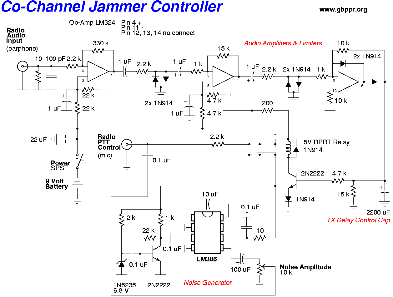
Figure 2: A Radio Frequency Jammer Circuit Diagram. Circuit Explanation. A simple jammer circuit can perfectly jam a wide range of radio frequency signals between 5 and 10 meters. An ideal radio frequency jamming equipment features 22pF trimmers to facilitate effectively blocking the RF noise signal.
