Home Built Geiger Counter Radiation Detector Circuit Diagram
Home Built Geiger Counter Radiation Detector Circuit Diagram The electronic circuit of a Geiger-Müller counter. MC34063 is a DC/DC converter used to produce required high voltage, one of it's advantage over a simple NE555 or similar generators in this circuit is that it can monitor the output voltage and adjusts parameters to make it stable (R3, R4, R5, C3).
This DIY nuclear radiation detector can measure and detect alpha, beta, and gamma radiation. Here we used muller tube, Geiger counter & ESP32. Making Portable Radiation Detection Device. By Ashwini Sinha. December 13, 2022. Telegram. Facebook. Linkedin. Here we used the muller tube and Geiger counter circuit to get the nuclear radiation.
Simplest Geiger Counter : 7 Steps (with Pictures) Circuit Diagram
Too make this Geiger counter work, there needs to be two parts of this circuit; the high voltage power supply, and the detector circuit. In the diagram above, the high voltage circuit consists of a 555 timer driving oscillator driving a transformer. The 555 timer generates a square wave that, through a resistor, turns on and off a MOSFET The circuit diagram is shown in Figure 6. The parts needed are shown in Figure 7 and parts lists broken down by subassembly are given at each step. You will be assembling the circuit on a printed circuit board (PCB), the top of which is shown in Figure 8. In the subsequent steps, components involved in the active step will be shown in full
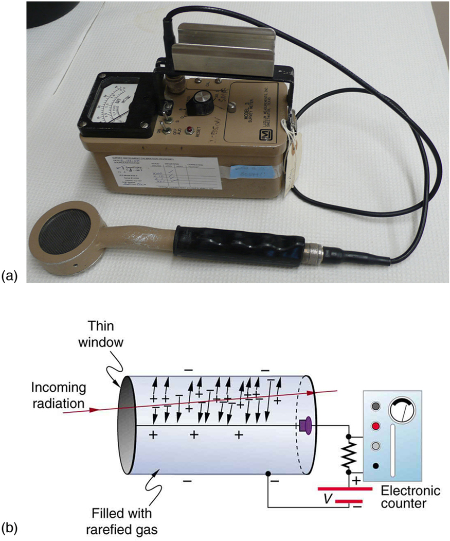
The key principal of Geiger counter operation is the Geiger tube, and how it sets up a high voltage on one electrode. This high voltage is like a steep mountain slope covered in deep snow, and all it takes is a tiny bit of radiation energy (akin to a skier going down the slope) to set off an avalanche.

Homemade Geiger Counter Circuit Diagram
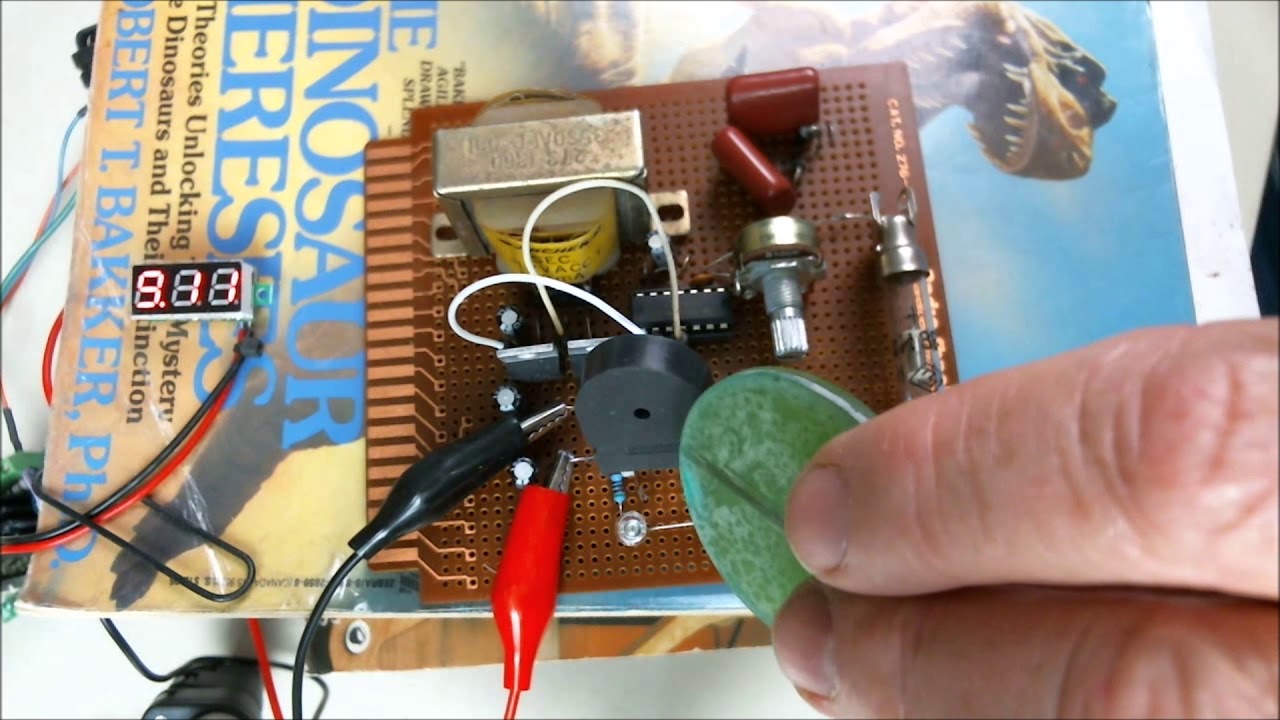
The 555 timer then drives a small speaker directly, making a 'click' noise each time the Geiger tube detects radiation. Use an IC socket for the 555 timer chip, so you don't fry the chip when trying to solder it into the circuit, also it makes it easier to replace if you make a wrong connection and fry the chip.
