Heres a short and sweet introduction on Bridge Rectifiers Circuit Diagram
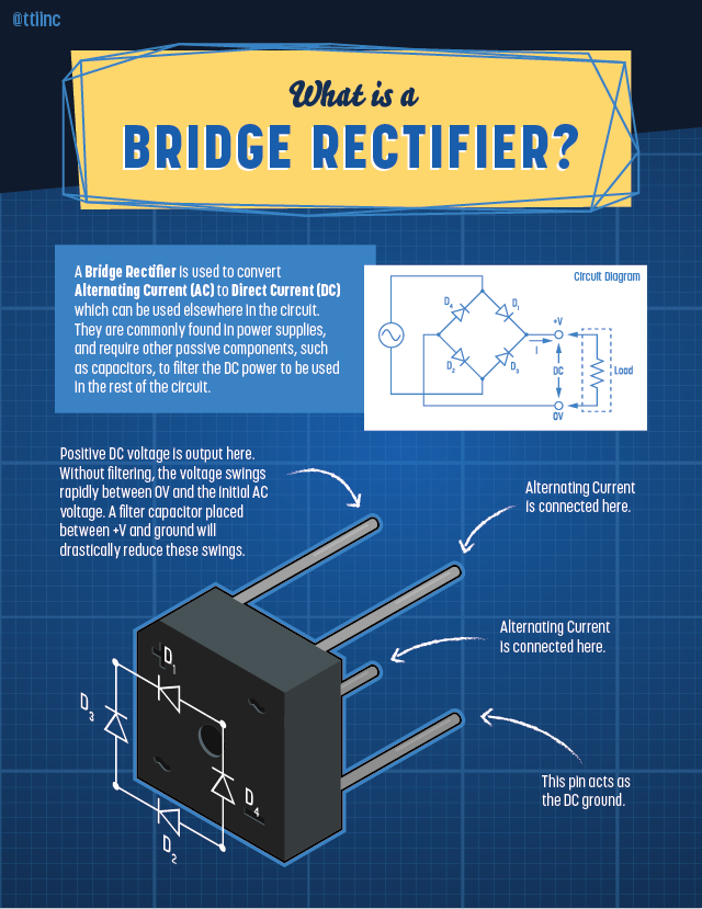
Heres a short and sweet introduction on Bridge Rectifiers Circuit Diagram The bridge rectifier converts alternating current (AC) into direct current (DC) through a bridge structure composed of four diodes. The unidirectional conductivity of the diodes is used to rectify the positive and negative half cycles of the AC into DC in the same direction. The design of the bridge rectifier not only improves the rectification efficiency but also provides a stable DC output 4. Simple Diode Bridge Rectifiers. Diode bridge rectifiers, sometimes referred to simply as bridge rectifiers, utilize diodes (uncontrolled semiconductor devices that allow current to flow in one direction only) to convert alternating current (AC) into direct current (DC). This type of rectifier is a staple in numerous electronic devices, from What is a Diode Bridge Rectifier? Basics of Diode Bridge Rectification. A diode bridge rectifier is a specific arrangement of diodes that converts AC to DC. This conversion is essential in many electronic devices, providing a consistent DC voltage from an AC power source. The full wave bridge rectifier consists of four diodes arranged in a
A full-wave bridge rectifier employs four diodes in a bridge configuration. During the positive half-cycle, diodes D1 and D2 conduct, allowing current to flow through the load. In the negative half-cycle, diodes D3 and D4 conduct, again allowing current to flow. This results in a smoother DC output with less ripple compared to a half-wave
Understanding the Bridge Rectifier with Zener Diode Circuit Circuit Diagram
A bridge rectifier consists of four diodes arranged in a bridge configuration. This setup allows the current to flow in one direction only, regardless of the polarity at the input. By arranging diodes in this specific pattern, the bridge rectifier effectively "rectifies" the alternating current (AC) into direct current (DC), a process that is essential for powering most electronic devices.
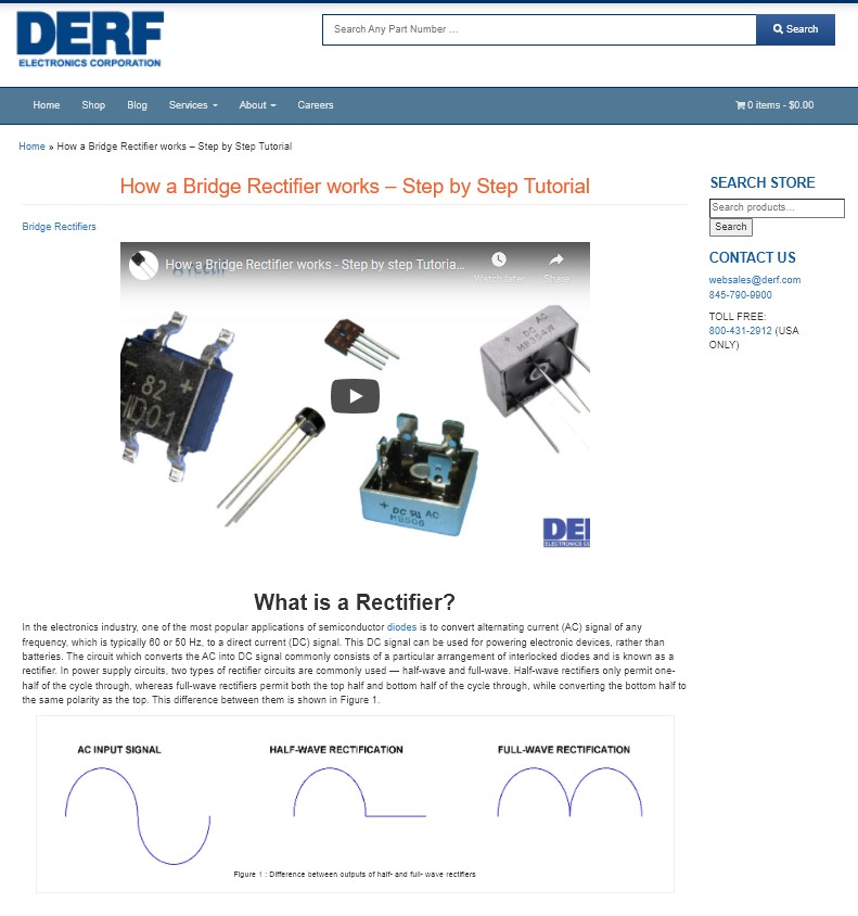
The Rectifier Diode. The diode bridge rectifier circuit is a very simple circuit made up of just four rectifier diodes connected in a square shape. A diode allows current to flow in one direction only (from the anode and to the cathode), which makes it perfect for converting from AC to DC. By the end of this comprehensive guide, you will have a thorough understanding of how diode bridge rectifiers work and why they are indispensable in various electronic systems. Definition and Overview. A diode bridge rectifier is an electronic circuit designed to efficiently convert AC voltage into DC voltage. It achieves this by utilizing four
Diode Bridge: Four Diodes That Convert From AC to DC Circuit Diagram
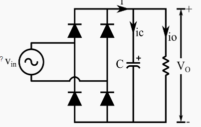
However, it is to be noted that the bridge rectifier's DC will be pulsating in nature. In order to obtain a pure form of DC, one has to use a capacitor in conjunction with the bridge circuit (Figure 4). In this design, the positive pulse at the input causes the capacitor to charge through the diodes D 1 and D 3.However as the negative pulse arrives at the input, the charging action of the The bridge rectifier portion of the circuit consists of four diodes arranged in a bridge configuration. These diodes convert the AC input voltage into a pulsating DC voltage. The output of the bridge rectifier is a series of positive voltage pulses, with the negative half-cycles of the AC waveform being inverted to positive.