A bit more detailed book on Diode circuits rElectricalEngineering Circuit Diagram
A bit more detailed book on Diode circuits rElectricalEngineering Circuit Diagram The proper use and connection of a diode are crucial for its right and reliable functionality. Understanding the rating and identifying the polarity is essential for diode proper usage. But the question is how to use a diode properly? It's always recommended to consult the diode's datasheet or seek expert advice when designing circuits In the devices you use, full-wave rectifiers are what are most commonly used to convert AC voltage to DC voltage. A full-wave rectifier circuit made with diodes is called a diode bridge. Check out the diode bridge in the circuit below: The diode bridge consists of four diodes - D1, D2, D3, and D4 - that are connected together.

Air Ionizer. The above voltage doubler when extended to many more stages using diodes and capacitors, to form a ladder, it ultimately constitutes a very special device called the air ionizer circuit.. This configuration mainly uses the rectification and blocking feature of the diode, and the charge multiplying feature of the capacitors, to form a high negative voltage generator circuit which
Diode Bridge: Four Diodes That Convert From AC to DC Circuit Diagram
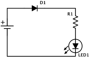
The diodes will also provide a voltage drop into the circuit. For example when I added this diode into a simple LED circuit mounted to a breadboard, I get a voltage drop reading of 0.71V. Why We Use Them. As mentioned we use diodes to control the direction of current flow in a circuit. Fortunately, there are pre-built diode bridge modules ready to use that already incorporate the necessary diodes and circuit configuration for efficient AC-to-DC conversion. Here you have some examples of diode bridge modules with different packings: Pre-built modules ensure consistent performance, are compact in size, and simplify integration. Zener diodes are doped with a higher concentration of impurities to give them a very thin depletion layer. In use they are reverse biased. This means that current cannot move across a zener diode until the breakdown voltage is reached. In any diode, there comes a point where, if sufficient reverse voltage is applied, reverse current will flow from cathode to anode.
The Schottky diode has a relatively small voltage drop, usually between 0.15 to 0.45 V. This low forward voltage enables it to switch on and off much faster than traditional PN junction diodes. How to Use Schottky Diodes. The Schottky diode works like any other PN junction diode, but faster. Current can flow through it only when it's forward The maximum power rating P Z of the zener diode is 2W. Using the zener regulator circuit above calculate: a). The maximum current flowing through the zener diode. Diode clipper circuits are also called limiters because they limit or clip-off the positive (or negative) part of an input AC signal. As zener clipper circuits limit or cut-off
